
How to 3D Print Lenticular Images?
How to 3D Print Lenticular Images? It starts with a small but important distinction: a lenticular image is usually made by aligning interlaced image views with a ridged lens sheet. A 3D printer can produce the lens structure or a physical image surface, but it does not automatically create the viewing effect. The alignment must be designed and tested.
Adrian Bowyer, founder of the RepRap project, is an established additive-manufacturing expert. I could not verify a lenticular-specific quotation from him, so this guide does not put invented words in his mouth. His work points to a useful principle: make digital designs repeatable and testable. Here, that means measuring the lens pitch, matching it to the interlaced artwork, and checking the print with a real sample. Tiny pitch errors can blur the image or make its depth jump.
The guide will cover preparing multiple views, converting them into interlaced strips, selecting a print method, and calibrating the lens-to-image spacing. A simple test print can reveal more than a perfect-looking screen preview. Hold it under a desk lamp. Tilt it slowly. If the image flickers between views, revisit the pitch and alignment before printing a larger piece. Some printers may struggle with fine ridges; that is worth acknowledging, not hiding. The practical goal of 3D Print Lenticular work is a stable, view-changing image—not merely a textured print.
What Lenticular Images Are and How They Create a 3D Effect
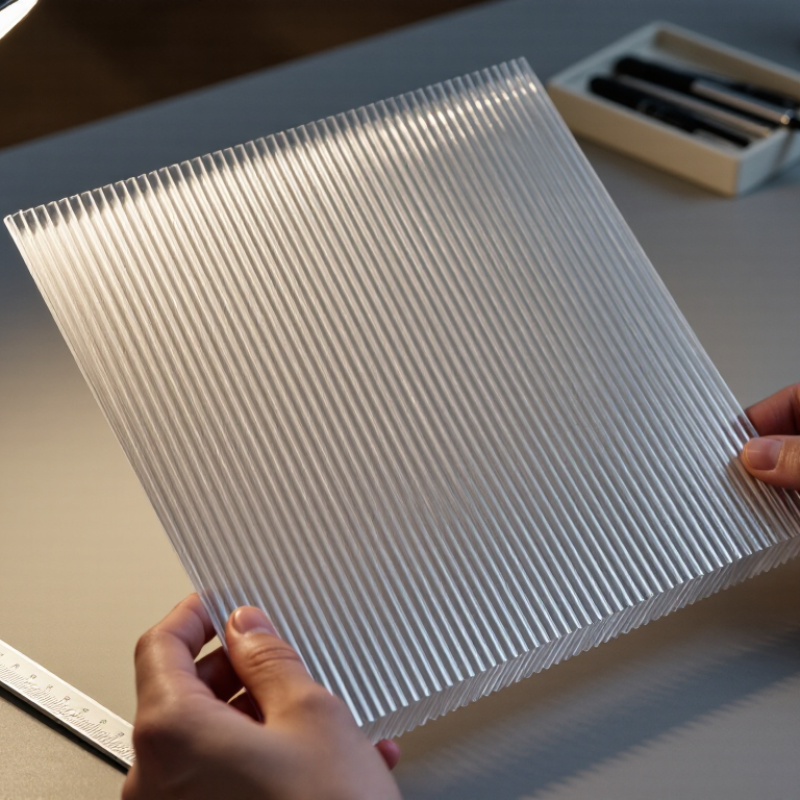
Lenticular images create the illusion of depth without moving parts. A sheet of fine, parallel lenses sits over an image divided into narrow strips. Each lens directs different strips toward different viewing angles. Your left and right eyes therefore receive slightly different views, much like they do when looking at a real object. The brain combines those views into a sense of depth. Small shifts can also reveal motion.
For a 3D-printed version, prepare several views of the subject, each from a slightly different camera position. Software interlaces those views into thin bands matched to the lens pitch. Print the image layer, then align it carefully with the lenticular sheet. Pitch matters. Even a small mismatch can produce ghosting, doubled edges, or a blurry effect. Test a small sample before printing a larger piece.
A printed lens may be possible, but its ridges need consistent spacing and a smooth surface. Layer lines can scatter light and weaken the image, so a separate optical sheet often gives clearer results. Keep the subject simple: a toy car with visible space between it and the background is easier to read than a crowded scene. The effect can feel subtle. That is not always a failure; dramatic depth may require more views and tighter alignment than a small printer can manage.
| Dimension | What It Means | Practical Guidance | Example or Check |
|---|---|---|---|
| Lenticular image | A composite image made by combining narrow strips from multiple views. A lenticular lens directs different strips toward the viewer at different angles. | For a depth effect, capture or render several views of the same subject from slightly different horizontal positions, then interlace them into one image. | Moving your head changes which view reaches each eye, creating a perception of depth and motion parallax. |
| 3D printing approach | The image and the lens can be produced separately, or the lens-like surface can be printed as part of the object. | A practical workflow is to print the interlaced image, then align it with a clear lenticular sheet. Printing the lens directly requires suitable geometry and a surface clear enough to guide light reliably. | Ordinary printed layer lines can scatter light, so a directly printed lens may look less clear than a purpose-made optical sheet. |
| View generation | Each source view represents the subject from a different camera position. The views are combined before printing. | Keep the subject, lighting, and background consistent between views. Use a modest camera shift for a shallow, comfortable depth effect; excessive shifts can cause ghosting or visual strain. | For a simple test, use a small number of views and inspect the result before producing a larger image. |
| Lens pitch | Pitch describes the number of lenticules per unit length, commonly stated as lenticules per inch (LPI). | Match the interlaced image pitch to the lens pitch. Calibrate with a test print because printer scaling, image resampling, and alignment can affect the result. | A 40 LPI lens has a nominal pitch of 25.4 ÷ 40 = 0.635 mm per lenticule. |
| Interlacing and alignment | Interlacing divides the views into strips and arranges them to correspond with the lens ridges. | Set the strip spacing from the measured lens pitch and the intended print scale. Align the lens ridges with the interlaced strips; even a small rotation or shift can mix views. | Look for a stable image when viewed from the intended direction. Blended views or repeated bands often indicate a pitch or alignment mismatch. |
| Printed lens geometry | A direct-print lens uses repeated curved or faceted ridges to refract light from different image strips. | Use a lens profile designed for the chosen viewing distance and image layout. Check the printer’s dimensional accuracy and surface finish, and test a small sample first. | There is no single ridge height or profile that works for every printer, material, lens pitch, and viewing distance. |
| Print orientation | The lens ridges must run in the correct direction relative to the interlaced strips. | For a typical horizontal-parallax effect, the views differ horizontally and the lenticules are arranged vertically. Follow the orientation used by the interlacing layout. | If the ridge direction and strip direction do not correspond, the image may show the wrong views or fail to produce the intended effect. |
| Viewing and quality checks | The effect depends on the lens, image, alignment, illumination, and viewing position working together. | Test under even lighting and view from several horizontal positions. Check for visible striping, ghosting, color shifts, and whether the depth direction appears correct. | Adjust one variable at a time—such as scale, alignment, or view spacing—so the cause of a change is easier to identify. |