
Industrial plants rarely fail at convenient moments. A control cabinet may sit beside a variable-speed drive, with long sensor cables, electrical noise, and temperature swings. In that setting, choosing a Digital Signal Isolator is not just a matter of comparing channel counts. Engineers must examine isolation rating, data rate, propagation delay, common-mode transient immunity, power needs, and package constraints. The right device depends on the system.
Bruce Trump, a longtime analog engineer and technical writer at Texas Instruments, has discussed practical analog design challenges. The following is an editorial paraphrase, not a verbatim quotation: “Select isolation for real operating conditions, not a headline specification.” That distinction matters. A device with impressive isolation figures may still be unsuitable if its timing, supply arrangement, or transient performance does not match the application.
This guide examines what makes a Digital Signal Isolator a strong industrial choice in 2026. It compares key specifications and design trade-offs, then considers reliability in demanding environments. A useful shortlist should include application details, not just product claims. Check the datasheet. Check the system, too. Even careful selection has limits: PCB layout, grounding, and external protection can affect real-world performance. The following outline helps readers assess those factors before choosing a part.
2026 Best Digital Signal Isolator for Industrial Use?
What Is a Digital Signal Isolator?
A digital signal isolator transfers logic information between circuits without a direct electrical connection. Inside, a tiny capacitive or magnetic barrier carries encoded pulses across an insulating gap. The receiving side reconstructs the signal. That gap matters. It helps block hazardous voltage differences, ground loops, and fast electrical transients from reaching sensitive control electronics.
In a factory, imagine a motor drive switching beside a temperature sensor. Noise can distort the sensor’s readings or upset a controller. An isolator separates the signal path while preserving its digital timing. IEC 60747-17:2020 covers magnetic and capacitive couplers used for electrical isolation; its framework makes insulation performance more than a simple “voltage rating.” Engineers also need to check working voltage, surge conditions, creepage distance, and clearance. IEC 60664-1:2020 uses 2,000 metres as the baseline altitude for clearance coordination; installations higher up may need correction. Not magic. A device can still fail if its layout, power supply, or PCB spacing is poorly chosen. I would compare channel count, data rate, isolation rating, and common-mode transient immunity against the actual system conditions. The awkward part: datasheet numbers rarely capture every switching spike on a real production floor. Test the assembled design, not just the component.
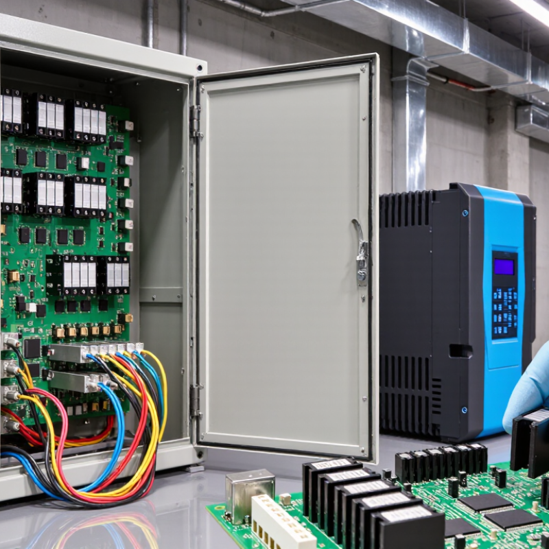
In an industrial control cabinet, a digital signal isolator transfers logic across an electrical barrier without a direct conductive path. Capacitive or magnetic coupling carries encoded pulses; circuitry on the other side rebuilds the signal. A sensor’s switching edge can therefore reach a controller while hazardous ground differences stay separated. Think of a motor encoder beside a variable-speed drive: the isolator helps block interference and ground-loop currents. It does not repair noisy wiring. That distinction matters.
IEC 61000-4-4 specifies electrical fast-transient immunity testing using pulses with a 5-nanosecond rise time and 50-nanosecond duration. Its test levels range from 0.5 to 4 kilovolts, depending on the port and installation conditions. These are test conditions, not an isolator’s guaranteed operating limits. Check working voltage, transient rating, common-mode transient immunity, channel timing, and isolation capacitance against the actual system. Easy to miss. A design can pass a bench test yet fail beside a contactor, where cable routing and grounding change the noise environment. Standards guide selection; measured cabinet behavior still deserves attention.
Conceptual signal path: an isolator transfers digital logic across an electrical isolation barrier. The output reproduces the input state after a propagation delay. The 5 ns offset shown is illustrative, not a product specification or measured benchmark.
Industrial designs should be selected against the required isolation rating, working voltage, propagation delay, data rate, common-mode transient immunity, and applicable safety standards.
For industrial use in 2026, start with the electrical environment, not the headline data rate. A digital signal isolator beside a motor drive may face fast voltage transients and severe common-mode noise. Check the required isolation rating and common-mode transient immunity, or CMTI, against the system’s actual conditions. Isolation voltage alone does not describe every operating risk. Noise is physical.
Then compare data rate, propagation delay, and channel-to-channel skew. A fast link can still cause timing trouble when several signals must arrive together. For encoder feedback or synchronized control, low skew may matter more than a large maximum data-rate figure. Check whether the stated performance holds across the full operating temperature range and supply-voltage range. A cabinet can run hot, and its supply may not stay perfectly steady.
Also review power consumption, channel count, package, and board-level spacing requirements. The isolator’s specifications do not replace careful PCB layout; nearby switching nodes and long traces can undermine a sound component choice. Confirm that relevant safety approvals match the end equipment and application, rather than assuming one rating covers every installation. I have seen peak speed get too much attention in design reviews. It is an easy number to compare, but not always the one that prevents a field failure._MARGIN matters.
For industrial use, compare digital signal isolators against the actual conditions at the control cabinet, not just headline data rates. Check the working isolation voltage and transient rating, then confirm they suit the system’s voltage and installation category. Common-mode transient immunity matters near variable-speed drives, where fast switching can disturb logic signals. That matters. Compare propagation delay and channel-to-channel skew if several outputs must stay synchronized. A faster part is not automatically the better choice.
Next, review the full operating temperature range, supply voltage, input thresholds, and output drive capability. For example, a sensor signal may travel across a long cable beside motor wiring; noise margin and board layout matter as much as the isolator’s specification. Check package size, creepage and clearance requirements, and whether the device’s safety documentation matches the intended design. Do not treat a certification mark as a substitute for system-level review. Datasheets can be easy to compare, but test conditions differ. I would avoid ranking parts by one number alone. Bench-test the candidate with the real cable, load, and switching noise where possible, and record any unexpected resets or timing changes.
| Comparison Dimension | Capacitive Digital Isolator | Magnetic Digital Isolator | Optocoupler | Industrial Selection Check |
|---|---|---|---|---|
| Isolation mechanism | Transfers digital signals across an insulation barrier using capacitive coupling. | Transfers digital signals across an insulation barrier using magnetic coupling, commonly through integrated transformer structures. | Transfers signals using light emitted by an LED and detected across an optical barrier. | Confirm that the isolation technology and package construction suit the required safety classification and system architecture. |
| Data rate | Available in low-speed and high-speed variants; maximum rate is specific to the device. | Available in low-speed and high-speed variants; maximum rate is specific to the device. | Ranges from relatively low-speed devices to high-speed types; performance depends strongly on the optocoupler design and circuit. | Compare the guaranteed maximum data rate with the protocol rate, required margin, and worst-case operating conditions. |
| Propagation delay and timing | Delay, pulse-width distortion, and channel-to-channel matching vary by device and data rate. | Delay, pulse-width distortion, and channel-to-channel matching vary by device and data rate. | Delay and pulse-width distortion vary by device and can be affected by LED drive and output circuitry. | Check maximum propagation delay, pulse-width distortion, skew, and timing over the full temperature range. |
| Common-mode transient immunity (CMTI) | Specified by the individual device; fast common-mode transitions can challenge signal integrity across any isolation barrier. | Specified by the individual device; performance depends on the barrier design and test conditions. | Specified by the individual device and circuit; layout and parasitic capacitance can affect transient performance. | Compare the guaranteed CMTI rating and test conditions with expected switching transients in the application. |
| Isolation ratings | Working voltage, withstand voltage, creepage, and clearance are product- and package-specific. | Working voltage, withstand voltage, creepage, and clearance are product- and package-specific. | Working voltage, withstand voltage, creepage, and clearance are product- and package-specific. | Do not infer safety performance from the coupling method alone. Verify the exact ratings and applicable approvals in the datasheet. |
| Power and interface requirements | Usually requires supplies on both sides of the barrier; consumption depends on data rate, channel count, and device design. | Usually requires supplies on both sides of the barrier; consumption depends on data rate, channel count, and device design. | Requires LED drive current and an output-side circuit; total power depends on the LED current and output configuration. | Compare total power at realistic switching activity, supply voltage, and temperature—not just a headline typical value. |
| Lifetime and aging | Does not rely on an LED transfer path; operating life is still limited by device ratings and environmental conditions. | Does not rely on an LED transfer path; operating life is still limited by device ratings and environmental conditions. | LED light output can decrease with time and operating stress, which may affect transfer performance. | For long-life equipment, review lifetime data, operating temperature, stress conditions, and any required design margin. |
| Channel options | Single- and multi-channel configurations are available; channel direction and isolation arrangement vary by device. | Single- and multi-channel configurations are available; channel direction and isolation arrangement vary by device. | Single- and multi-channel packages are available; channel count and direction depend on the package. | Match channel count, direction, logic polarity, and package pinout to the design to reduce extra circuitry. |
| Fail-safe behavior | Default output state during input loss or power loss is device-specific. | Default output state during input loss or power loss is device-specific. | Output behavior depends on the optocoupler output type and external circuit. | Verify output state during startup, shutdown, and loss of either-side power; choose a defined safe state where required. |
| Industrial environment | Temperature range, package robustness, and electrical limits vary by device. | Temperature range, package robustness, and electrical limits vary by device; assess magnetic-field exposure if relevant. | Temperature range and package robustness vary by device; account for LED aging and the surrounding circuit. | Check the specified temperature range, humidity and pollution assumptions, PCB layout rules, and expected electrical noise. |
| Typical application fit | Useful for compact, integrated digital isolation where the device’s ratings and transient performance meet the design needs. | Useful for integrated digital isolation where the device’s ratings, transient performance, and field environment are suitable. | Useful where optical isolation is preferred or an existing design uses optocouplers and their operating characteristics are acceptable. | There is no universally best option: select by verified safety ratings, timing, CMTI, power, lifetime, environment, and total system cost. |
Note: Ratings and performance are specific to each component, package, and test condition. Use the latest datasheet and applicable safety requirements for the final design; technology-level descriptions are not substitutes for component specifications.
Industrial digital signal isolators are commonly installed between control electronics and electrically noisy equipment. Inside a motor-control cabinet, they can separate a programmable logic controller’s output from a variable-speed drive’s input. This barrier helps limit the transfer of ground differences and fast electrical transients between circuits. Noise is real. Isolation does not replace proper grounding or overvoltage protection.
Factories also use isolators in remote I/O modules, sensor interfaces, and robotic equipment. On a packaging line, an isolated input can carry a photoelectric sensor’s on-off signal into a controller near motors and relays. In process plants, isolated channels help connect temperature or pressure transmitters to monitoring systems. They are also used in industrial power monitoring, where control signals and measurement circuits may have different ground references. The right placement depends on the circuit, not just the machine.
For a practical selection, check channel count, data rate, operating temperature, isolation rating, and common-mode transient immunity. Confirm that the package and board layout meet the required creepage and clearance distances. A high rating on paper is not enough if the PCB layout undermines the barrier. Field wiring is rarely textbook-clean, either; long cables and nearby switching loads can expose weaknesses that a bench test misses. Verify performance in the actual installation.
Join our mailing list to receive the latest news and updates from our team.