How to Choose the Right Cooler Cold Plate in 2026?
Choosing the right Cooler Cold Plate in 2026 requires more than comparing prices or surface dimensions. Modern cooling systems face tighter spaces, higher heat loads, and stricter energy targets. A plate that performed well in a 2023 prototype may struggle inside a newer electric vehicle inverter, data center server, or industrial laser.
The selection process begins with real operating conditions. Measure the heat load, coolant temperature, flow rate, pressure drop, and available mounting space. Copper can provide excellent thermal conductivity, while aluminum may reduce weight and cost. However, material compatibility deserves careful attention. Mixed metals, unsuitable coolants, or poor surface finishes can accelerate corrosion. Small details matter.
Fit comes first.
A reliable evaluation should include thermal resistance testing, leak inspection, pressure testing, and long-term cycling. Review the supplier’s drawings, manufacturing tolerances, test records, and quality controls. Ask how the cold plate performs when flow decreases or coolant temperature rises. These questions reveal more than a polished product sheet.
There is no universal best design. That is easy to forget. A microchannel plate may deliver impressive cooling, yet its narrow passages can increase blockage risks and maintenance demands. A simpler channel layout may offer easier service, even with slightly lower peak performance. Engineers should compare measured data with actual system needs, not ideal laboratory results. This guide examines key design choices, materials, flow structures, reliability concerns, and purchasing criteria to help readers make a practical decision in 2026.
Define Cooling Requirements: Size for 10–1000 W Heat Loads and Target ΔT
How to Choose the Right Cooler Cold Plate in 2026?
Start with the heat load, not the cold plate’s advertised capacity. Measure the device’s real thermal output during startup, sustained operation, and worst-case ambient conditions. A 10 W sensor module needs a different plate from a 1,000 W power converter. The 2024 United States Data Center Energy Usage Report estimated that U.S. data centers used 176 TWh in 2023. This rising demand makes accurate thermal sizing more important. For selection, calculate thermal resistance as Rθ = ΔT/Q. A 1,000 W load with a 10°C target rise requires approximately 0.01°C/W. That is demanding. Pump capacity, coolant temperature, contact pressure, and interface resistance can quickly consume the margin.
Target ΔT should reflect the most temperature-sensitive component, not the average assembly temperature. ASHRAE Thermal Guidelines recommend evaluating inlet conditions, humidity, and equipment operating limits together. A cold plate may remove heat efficiently while still creating local hotspots near a chip corner. Record temperatures at several points. Check the plate after thermal cycling. My first sizing pass is often too optimistic.
Tips: Add a 20–30% design margin when the load profile is uncertain. Use a calibrated power meter and thermocouples. Confirm flow at the plate inlet, not only at the pump. Keep hose bends short and inspect the mounting surface. Measure twice. Test at the warmest expected room condition, because a laboratory result can mislead field decisions.
Compare Plate Materials: Copper ≈385 vs Aluminum ≈205 W/m·K
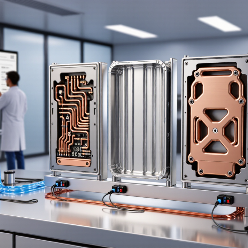
Thermal conductivity Choosing a cooler cold plate starts with thermal conductivity, but conductivity alone can mislead. Common design data place copper near 385 W/m·K and aluminum near 205 W/m·K at room temperature. These values align with references in ASM Handbook, Volume 2, and the Aluminum Association’s material data. Copper spreads heat more quickly across a compact plate. That advantage matters when a processor creates a concentrated hotspot.
Aluminum is lighter and usually easier to machine. Its density is about one-third of copper’s, according to ASM material property data. Weight matters in portable equipment and overhead assemblies. However, aluminum may need a thicker plate or improved channel layout. Thermal performance depends on more than the metal. ASHRAE Handbook guidance highlights contact resistance, coolant flow, surface finish, and temperature difference.
In practical testing, I would compare equal plate thicknesses first. That reveals copper’s spreading advantage clearly. Then compare equal weights. The result may change. A thin copper plate can outperform aluminum near the heat source, while a thicker aluminum plate may offer better structural value. This is where specifications can become imperfect. Alloy selection also changes conductivity, sometimes substantially. Check the supplier’s tested data, not only a catalogue average.
Select Channel Geometry: Balance Pressure Drop with 1–5 L/min Flow
How to Choose the Right Cooler Cold Plate in 2026?
Channel geometry controls how coolant moves, spreads heat, and consumes pumping power. For systems operating between 1 and 5 L/min, pressure drop should match the pump curve, not simply look as low as possible. Narrow serpentine channels improve contact time and temperature consistency. However, they can create excessive resistance at 5 L/min. Wider parallel channels reduce pressure drop, yet uneven flow may leave hot zones near the inlet or outlet.
In practical testing, measure pressure at the cold plate inlet and outlet with water near 20°C. Keep the same fittings, tubing length, and flow meter for every design. A 1 L/min test can reveal distribution problems, while 5 L/min exposes pump limitations. I have seen a plate perform well thermally but fail after installation because the manifold restricted flow. That mistake was avoidable. Geometry alone cannot explain the result.
Tips: Compare several channel widths using the full 1–5 L/min range. Check thermal uniformity at the actual heat load. Leave some pressure margin for filters, bends, and aging coolant. Do not trust simulation without physical validation. Test again after changing the inlet direction; small details matter.
How to Choose the Right Cooler Cold Plate in 2026?
Select channel geometry by balancing pressure drop with the required 1–5 L/min coolant flow range.
Pressure drop rises rapidly as flow increases. Wide parallel channels provide the lowest hydraulic resistance, while serpentine and pin-fin geometries improve heat transfer at the cost of higher pumping requirements. For most systems, select a geometry that meets the target heat load without exceeding the available pump pressure.
Validate Reliability: Test TIM, Corrosion, and 2026 Operating Conditions
How to Choose the Right Cooler Cold Plate in 2026?
Validate Reliability: Test TIM, Corrosion, and 2026 Operating Conditions
A cold plate should survive more than a short laboratory trial. The IEA’s Electricity 2024 report projects data-centre electricity demand to exceed 1,000 TWh by 2026. Higher rack power means hotter surfaces, faster cycling, and less tolerance for weak thermal interfaces. Test the TIM using ASTM D5470 methods. Measure thermal resistance before and after repeated heat cycles. A small pump-out gap can become a serious hotspot.
Coolant chemistry deserves equal attention. ASTM G31 immersion testing can reveal corrosion risks in channels, joints, and dissimilar metals. Use representative coolant, dissolved oxygen, temperature, and flow conditions. Do not test clean water only. Real systems may include inhibitors, particles, or maintenance errors. ASHRAE TC 9.9 guidance also supports checking inlet temperature, humidity, and dew-point margins. These conditions affect condensation and long-term reliability.
Tips: Record pressure drop beside thermal performance. A plate that cools well but restricts flow may overload the pump. Test at expected 2026 loads, then add a reasonable safety margin. Inspect the TIM thickness after cycling. This step is often skipped. It should not be. In practice, a polished report can still hide an uneven interface or an untested corrosion couple. That uncomfortable gap deserves review before selection.