Why Choose Steel Cable Tray for Global Projects?
Global projects demand cable support that survives transport, installation, weather, and years of maintenance. Steel Cable Tray remains a strong choice because it combines load capacity, dimensional stability, and familiar installation practices. Grand View Research’s Cable Tray Market Size, Share & Trends Analysis Report, 2024–2030, identifies infrastructure expansion and industrial construction as major market drivers. Its findings reflect a practical reality: more power and data cables require organized support systems.
The engineering case becomes clearer on site. A hot-dip galvanized tray can protect cable routes in humid plant rooms, rooftop corridors, and exposed utility areas. Stainless steel may suit severe coastal conditions. The correct material depends on corrosion exposure, span length, cable weight, and available access. NEMA VE 1 and IEC 61537 provide recognized requirements for cable tray construction and performance. UL 568 also supports safer product evaluation in applicable installations. Standards matter.
William A. Thue, a respected cable-engineering author, offers a useful design principle: “Cable tray is a support system, not a raceway.” That distinction affects fill, ventilation, bending space, and future additions. It also prevents a common mistake: treating every tray as interchangeable. Steel is not automatically the best answer. Poor coating selection can shorten service life. Weak bonding can create unnecessary risk. Global procurement also exposes differences in testing, tolerances, and installation habits. Therefore, project teams should verify certificates, load tables, coating specifications, and local approval requirements before ordering. The decision is less glamorous than product marketing suggests. It is still decisive.
What Is a Steel Cable Tray?
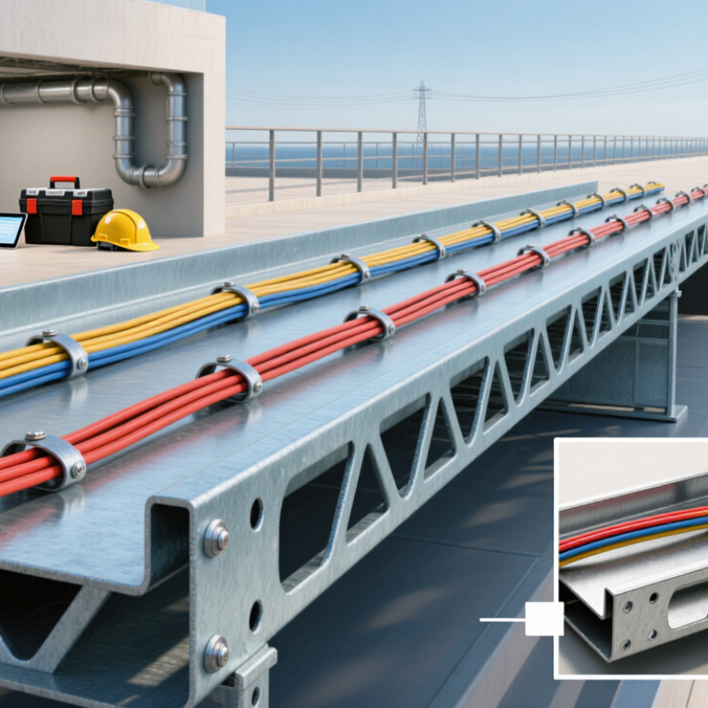
A steel cable tray is a prefabricated support system for routing power, control, and communication cables. It usually includes side rails, rungs, and connecting fittings. Perforated or solid-bottom designs serve different installation needs. Ladder trays improve ventilation, while solid bottoms offer added support for smaller cables. Common materials include galvanized steel, stainless steel, and coated steel. The right choice depends on corrosion exposure, cable weight, span, and maintenance access.
Unlike closed conduit, a tray allows technicians to inspect cables quickly. It also reduces heat buildup when spacing is designed correctly. NEMA VE 1 and IEC 61537 specify important requirements for loading, deflection, electrical continuity, and testing. These details matter on global projects. MarketsandMarkets’ 2024 Cable Trays Market report estimates the sector at approximately USD 4 billion, with continued growth expected through 2029. World Steel Association data also reports more than 650 million tonnes of steel recycled annually, supporting steel’s circular-use advantage.
Steel is strong, but it is not maintenance-free. Salt air, chemical vapors, and damaged coatings can accelerate corrosion. Engineers sometimes focus on tray strength and overlook bonding jumpers or expansion joints. That mistake can create expensive rework. Field teams should verify span tables, fastener materials, cable fill, and earthing continuity before installation. A tray is not a magic shield. It is a carefully engineered pathway.
How Steel Cable Trays Support Global Project Requirements
Steel cable trays support global project requirements because they adapt to varied environments and installation practices. Global projects rarely share the same site conditions. A tray crossing a humid port may face salt-laden air and condensation. In a dry inland plant, dust and high temperatures may matter more. This variation makes material selection a practical engineering decision.
From project experience, galvanized or suitably coated steel trays provide useful mechanical strength and predictable support. They can protect cables near pumps, switchgear, and maintenance walkways. International projects also demand clear load calculations, material certificates, and traceable inspection records. These documents help engineers verify compliance before shipment and installation.
At the site, installers need accurate dimensions and familiar accessories. Small details matter. A missing splice plate once caused avoidable rework during a tight shutdown window.
Steel trays can also support seismic, thermal, and fire-related design considerations when properly specified. Designers may add expansion joints where long runs cross temperature zones. In coastal locations, corrosion protection requires more than a thick coating. Drainage, fastener selection, and regular inspection deserve equal attention. No design is perfect. A heavy tray may improve durability but increase handling difficulty, support loads, and transport costs. Lighter options may simplify installation, yet they can reduce protection in exposed areas. That uncertainty belongs in the design review, not after installation.
Key Benefits of Steel Cable Trays in International Installations
Why Choose Steel Cable Tray for Global Projects?
International installations demand more than simple cable support. Steel cable trays provide high mechanical strength across long spans, crowded service corridors, and exposed plant areas. In field projects, installers can inspect routes quickly and add cables without rebuilding entire supports. That matters when labor skills and site conditions differ between countries.
The International Energy Agency’s Electricity 2024 report expects global electricity demand to grow by more than 6% from 2024 to 2026. More generation and distribution work means denser, more maintainable cable systems. Steel trays also support orderly separation of power, control, and communication circuits. IEC 61537 provides requirements for cable tray systems, while national electrical rules may add grounding, fire, and spacing requirements. Design teams must check both.
Corrosion remains the difficult detail. NACE International’s IMPACT study estimated global corrosion costs at about $2.5 trillion annually, equal to 3.4% of global economic output. Galvanized steel can suit many indoor and moderate outdoor environments, while heavier coatings or stainless steel may be needed near saltwater, chemicals, or persistent moisture. Coating choice should follow measured exposure, not habit.
Steel is not automatically best. That assumption deserves testing. A tray that survives transport but fails at a coastal site is still a poor specification. Engineers should verify loading, deflection, bonding, thermal movement, local compliance, and replacement access before approving the final route.
Why Choose Steel Cable Tray for Global Projects?
Key material properties supporting strength, fire performance, and long-term international installation reliability
Steel offers a high strength-to-cost ratio, non-combustible performance, and compatibility with widely recognized protection systems such as hot-dip galvanizing. The values shown are typical reference values for carbon steel and are provided for general engineering comparison; actual performance depends on grade, coating, fabrication, loading, and environmental conditions.
Reference basis: typical carbon-steel engineering data, ISO 1461 hot-dip galvanized coating requirements, and IEC 61537 cable-management-system testing principles.
Installation and Maintenance Considerations Across Different Regions
Steel cable trays suit global projects because they offer load capacity, routing flexibility, and practical repair options. Their value depends on installation discipline, not metal alone. Field experience shows that regional conditions often decide long-term performance.
On coastal sites, specify suitable corrosion protection and prevent water pockets. Drainage holes must remain open after cutting and fastening. Keep it dry.
In humid regions, inspect joints, bends, and exposed edges more often. Salt deposits can hide early coating damage.
Inland areas bring dust into covers and fittings. Clean them without damaging protective finishes.
In cold climates, allow movement for thermal expansion and contraction. A rigid run can stress supports unexpectedly.
Seismic zones require engineered bracing, flexible connections, and verified anchor capacities. Use qualified local engineers. Do not copy details from another country.
Installation crews should separate power and communication circuits according to regional electrical requirements. Maintain safe clearances around heat-producing cables. Bond tray sections correctly, then test continuity before energizing equipment. Labels should match local language and emergency practices. This small detail prevents confusion during repairs.
Maintenance records should note torque checks, coating condition, cable additions, and unusual vibration. We once found a loose splice hidden above a crowded ceiling. It had passed a visual inspection. That mistake changed our inspection method.
Measure twice. Good plans still need field judgment. Weather, labor skills, and replacement-part access can alter the schedule. Review those realities before final design approval.