
What Is a Control Valve and What Types Are There?
A control valve regulates flow, pressure, temperature, or liquid level by changing the passage through a process line. It receives a signal from a controller, then moves an internal element to adjust the amount of fluid or gas passing through. That movement may be subtle. A small change can affect an entire production line.
Process-control specialist Greg McMillan’s guidance can be paraphrased this way: a control valve turns a controller’s output into a physical change in process flow. The valve is not just a pipe fitting. Its performance depends on the valve body, trim, actuator, positioner, and the conditions around it. A sticky stem, for example, can make a stable control signal produce uneven flow. Real installations are messier than diagrams suggest.
This guide explains the main control valves and how their designs differ. It covers globe valves, often chosen for precise throttling, and rotary designs such as ball and butterfly valves. It also introduces diaphragm and pinch valves, which suit particular fluids and operating conditions. The right choice depends on more than the valve’s name: engineers consider pressure drop, flow range, materials, leakage needs, and maintenance access. There is no universal best type. A valve that performs well on a clean-water line may be a poor fit for an abrasive slurry. Understanding these trade-offs makes selection safer and more dependable.
What a Control Valve Is and What It Controls
What Is a Control Valve and What Does It Control?
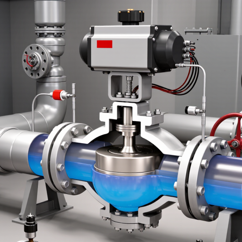
A control valve regulates a process by changing how much fluid can pass through a pipe. The fluid may be water, steam, air, or another process gas or liquid. A controller reads a measurement, such as temperature or pressure, then signals the valve’s actuator to adjust its opening. The valve therefore controls flow directly and can influence pressure, temperature, or liquid level indirectly. It is one part of a control loop, not a stand-alone decision-maker.
In a steam line, for example, a partly closed valve reduces steam flow to a heating coil. A temperature sensor reports the result, and the controller requests another adjustment if the coil remains too hot. The International Energy Agency’s Energy Efficiency 2023 report says industry uses about 37% of global final energy. That figure is not a measure of valve savings, but it shows why stable process control matters. A valve is not a magic efficiency fix; poor sizing, leaks, or unstable control can undermine performance.
Tips: Check the process fluid, operating pressure, temperature, and required flow range before selecting a valve. Verify the actuator and control signal match the system. Small details matter. A carefully chosen valve may still need tuning after installation, and real operating conditions can be messier than design assumptions.
What Is a Control Valve and What Types Are There? — What a Control Valve Is and What It Controls
A control valve is a final control element that varies the flow of a liquid, gas, steam, or slurry in response to a control signal. By changing flow, it helps regulate a process variable such as pressure, temperature, level, or flow rate. A separate sensor and controller usually measure the process and determine the valve’s requested position.
| Valve type | How it controls flow | Typical strengths | Common considerations | Typical services |
|---|---|---|---|---|
| Globe valve | A plug moves toward or away from a seat to throttle the flow passage. | Good throttling performance and precise flow control across a wide range of conditions. | Often has a higher pressure drop than some rotary valves; body and trim selection must suit the fluid and operating conditions. | Water, steam, gas, and process-fluid flow or pressure control. |
| Rotary ball valve | A rotating ball changes the opening; control versions may use a characterized or segmented ball. | Compact design, relatively high capacity, and quarter-turn operation. | A standard full-port ball valve is primarily intended for on/off service; suitable control performance depends on the control-valve design and trim. | Liquid and gas services where compact construction and useful throttling capacity are required. |
| Butterfly valve | A disc rotates within the pipe to vary the open area. | Lightweight, compact, and suitable for large pipe sizes; requires quarter-turn actuation. | Control range and shutoff performance depend on valve design, disc geometry, and operating conditions. | Water, air, and other compatible fluids in utility and process systems. |
| Diaphragm valve | A flexible diaphragm moves against a weir or seat to restrict or stop flow. | The process fluid can be isolated from many moving components; useful where cleanability or corrosion resistance is important. | Diaphragm materials and pressure-temperature limits must match the service; not every design is suited to high-pressure duty. | Water treatment, hygienic processes, and compatible corrosive or particulate-bearing fluids. |
| Rotary plug valve | A tapered or cylindrical plug rotates to align its passage with the flow path. | Simple rotary action and designs available for throttling or shutoff duties. | Sealing, torque, and resistance to wear depend on the plug design, materials, and fluid properties. | Liquids and gases in general process and utility applications. |
| Pinch valve | An actuator compresses a flexible sleeve to reduce or close the flow passage. | The fluid contacts the sleeve rather than a complex internal trim; can handle some slurries and solids-laden flows. | Sleeve compatibility, wear, and pressure limits are key selection factors. | Slurries, powders in suitable conveying arrangements, and abrasive or particulate-bearing fluids. |
| Angle valve | A globe-style plug and seat control flow through a body with an angled inlet and outlet. | Can change flow direction within the valve body and may suit services where drainage or reduced piping complexity is useful. | Pressure drop and flow capacity depend on the valve geometry and installation. | Steam, condensate, and other process services where an angled flow path is beneficial. |
What it controls: A control valve directly manipulates fluid flow. In a feedback control loop, changing that flow can regulate flow rate, downstream pressure, temperature, or liquid level. The required valve type and materials depend on factors such as fluid properties, pressure, temperature, flow range, and the desired control accuracy.
Related Posts
-

Essential Control Valves Maintenance Checklist for Optimal Performance
-

Ultimate Guide to Choosing the Right Electric Valves for Your Industrial Needs
-
Why Electric Valves are Essential for Efficient Fluid Control Systems
-
Why Choose Electric Valves for Industrial Applications?
-
Understanding the Future of Automated Valves in Modern Industry Technology
-
How to Choose Actuated Valves in 2026?