A valve may look like a small part of a plant, but its actuator can shape how reliably a process runs. Electric valves use an electric actuator to position the valve in response to a control signal. That makes them useful where operators need repeatable flow control, remote adjustment, or clear feedback from equipment on the line. Think of a dosing skid: a precise valve movement can help maintain a steady feed, while reducing the need for routine manual adjustments.
The case is practical, not automatic. Electric actuation can avoid the instrument-air supply required by pneumatic systems, but energy use, response time, torque, fail-safe behavior, and maintenance needs still matter. Site conditions matter, too. A corrosive washdown area calls for different protection than a dry control room. The International Energy Agency’s Energy Efficiency 2023 report says energy efficiency must improve by more than 4% annually this decade to align with its net-zero pathway. That is a system-wide target, not a promised saving from any single valve. IEA Executive Director Fatih Birol has described energy efficiency as “the first fuel.” His phrase captures the wider goal, though equipment choices need their own evidence. For engineers comparing electric valves, the useful question is specific: will the actuator improve control and reliability in this service, at an acceptable lifecycle cost? Sometimes the honest answer is not yet. The following sections examine the operating advantages, selection criteria, and trade-offs behind choosing electric valves for industrial applications.
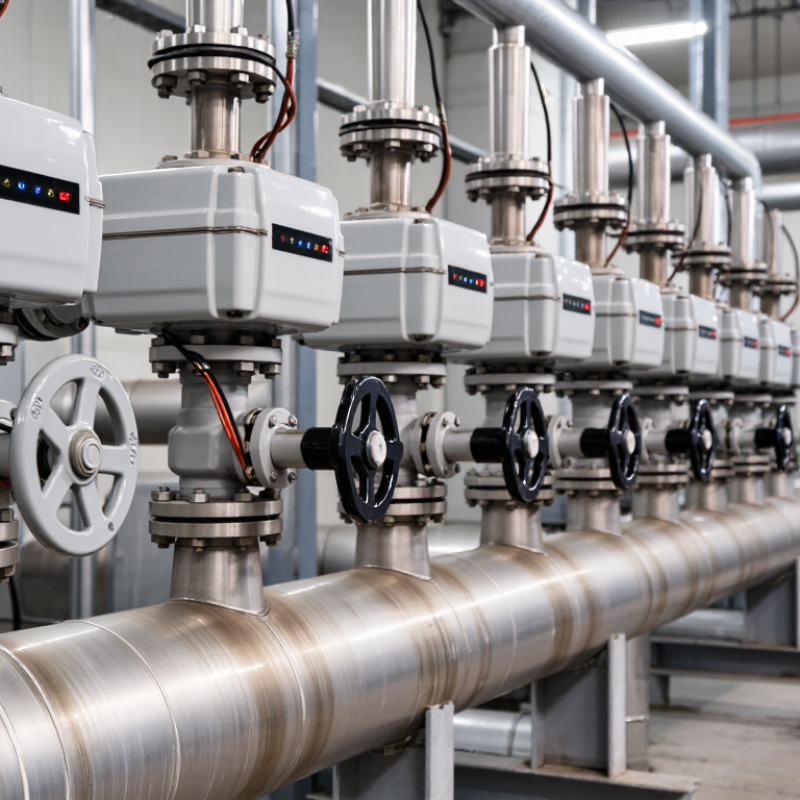
An electric valve combines a valve body with an electric actuator. The body guides or stops fluid; the actuator turns electrical energy into motion. A small motor may rotate a ball valve or move a stem in a globe valve. The result can be simple open-and-close operation or controlled flow adjustment. It depends on the valve design.
A controller sends a command, often through a wired signal, and the actuator moves toward the requested position. Many units use limit switches or position feedback to show when the valve is open, closed, or partly open. On a plant floor, this can let an operator adjust a cooling-water line without walking to a hot pipe. Not every electric valve responds equally fast. Sizing, pressure, and fluid conditions matter. A shutoff valve is not automatically a precise flow-control valve.
Tips: Check actuator torque against the valve’s operating load, and confirm the supply voltage before installation. Test the full travel with the line safely isolated. Also ask what happens during a power loss; an electric actuator does not necessarily move to a safe position. It’s an easy detail to overlook.
An electric valve uses an electrically powered actuator to move the valve stem or shaft. In modulating applications, the actuator receives a position command and can use feedback to adjust valve travel. The chart shows illustrative command points—not measured performance data—to explain the relationship between a position command and valve travel.
Electric valves give operators precise control over flow without relying on a compressed-air supply. Their actuators can open, close, or position a valve in response to local controls or remote signals. That helps when a process needs repeatable adjustments, such as regulating cooling water through a pipe loop. Operators can also check position feedback from a control room instead of walking to every valve.
They fit naturally into automated systems. An electric actuator can connect with sensors and controllers, allowing valve movement to follow measured pressure, temperature, or flow. Fewer air lines can also simplify installation in some plants. Less infrastructure, sometimes. The trade-off is easy to overlook: electric valves depend on reliable power, and response speed varies by actuator and application. A power loss may leave a valve in its last position unless a suitable backup or fail-safe design is specified. Sizing matters, too. A valve that looks adequate on a drawing may struggle against real operating pressure. Before installation, engineers should verify torque requirements, duty cycle, environmental protection, and manual operation needs. These details can take time, but skipping them often creates avoidable maintenance work.
Electric ball valves use a quarter-turn motion to open or close flow quickly. They are common in water lines, compressed-air systems, and process skids where reliable shutoff matters. With a suitable actuator and control signal, some models can regulate flow, though not every ball valve is designed for continuous throttling. Quick response matters.
Electric butterfly valves also turn a disc inside the pipe. Their compact bodies suit large cooling-water lines, HVAC loops, and wastewater treatment equipment, where space and weight can matter. Electric gate valves are often used for isolation in pipelines and utility systems. They should generally be fully open or fully closed, not used to finely adjust flow. Electric globe valves offer more controlled throttling in steam, fuel, and process-fluid lines, but their pressure drop can be higher. Diaphragm valves can handle certain corrosive or contamination-sensitive fluids when their wetted materials are compatible. That sounds simple. It rarely is. In practice, fluid temperature, pressure, pipe size, and cycling frequency all affect valve choice. A hurried selection may fit the drawing but perform poorly once the line heats up or debris builds around the seat.
Choosing an electric valve for a specific process starts with the fluid, not the pipe diameter. Record the operating pressure, temperature, flow range, and whether the media contains particles or corrosive components. A valve sized only to match the pipe can cause poor control or excessive pressure loss. Details matter.
Next, match the valve body and trim materials to the fluid, then choose a valve type suited to the task. Ball valves often suit on-off service, while globe valves can provide more precise throttling. Check the actuator’s torque against the worst expected pressure differential, not just normal conditions. Also confirm voltage, control signal, enclosure protection, and operating cycles per hour. A warm, damp pump room needs different protection from a clean indoor panel.
Consider what should happen if electrical power fails. Many electric actuators stay in their last position unless equipped with a suitable return mechanism or backup supply. That behavior must fit the process risk. It is easy to overlook manual access during maintenance, especially when valves sit behind pipework. Finally, test the selected assembly under realistic operating conditions; catalog figures alone may not capture startup surges or changing fluid viscosity. A selection can look right on paper and still need adjustment in the field.
Electric valves work well when their installation matches the process, not just the pipe size. Check the valve’s pressure and temperature limits, flow direction, and required torque before mounting it. Leave room to remove the actuator cover and reach the terminals. Support the pipe so its weight does not strain the valve body. Small details matter.
Before wiring, isolate the power supply and confirm the control signal and voltage match the actuator specifications. During commissioning, test the full stroke and verify that the valve reaches its intended position when power or signal is lost. A valve that moves during a bench test may behave differently under process pressure. That assumption can be wrong. Record the tested settings so later adjustments do not become guesswork.
Maintenance should follow operating conditions and cycle frequency. Inspect cable entries for moisture, check terminals for looseness, and look for corrosion or unusual actuator noise. Compare position feedback with the actual valve movement; a mismatch can point to wiring, calibration, or mechanical issues. Keep a simple service log with dates, observed faults, and corrective work. Not every fault is the valve’s fault, though. Check the controller and power supply before replacing components.
| Consideration | Electric Valve Characteristics | Practical Application and Checks |
|---|---|---|
| Operating principle | An electric actuator converts electrical energy into mechanical motion to operate a compatible valve. Actuator designs include quarter-turn and multi-turn types. | Match the actuator’s motion and output torque or thrust to the valve’s operating requirements, including the torque needed to unseat the valve. |
| Power supply | Actuators are available for different supply voltages and AC or DC power. Motor current can increase during starting or demanding operating conditions. | Confirm the available voltage, frequency, wiring arrangement, and supply capacity. Follow the actuator documentation and applicable electrical codes. |
| Installation space | Electric actuation generally requires electrical connections and clearance for the actuator enclosure, wiring, and any local controls. | Check mounting orientation, access for wiring and service, pipework clearance, and protection from heat, vibration, flooding, or corrosive exposure. |
| Position control | Depending on the actuator and controls, operation can be on/off or modulating. Modulating systems may use signals such as 4–20 mA or 0–10 V. | Specify the required control mode, input and feedback signals, positioning accuracy, and response time. Confirm compatibility with the control system. |
| Automation and feedback | Limit switches, position transmitters, and communication interfaces may provide valve status or position information when included in the selected configuration. | Identify which signals are needed for alarms, interlocks, or supervisory control. Verify signal type, wiring, and feedback behavior during commissioning. |
| Fail-safe behavior | A standard electric actuator may remain in its last position when power is lost. A defined fail position requires an appropriate design, such as a spring-return actuator or backup energy source. | Assess the process risk and required safe state before selection. Test loss-of-power behavior and emergency operation as part of commissioning. |
| Operating environment | Enclosure protection, temperature limits, corrosion resistance, and hazardous-area suitability vary by actuator configuration. | Select ratings for the actual site conditions. Do not assume an enclosure or actuator is suitable for washdown, outdoor exposure, or hazardous locations without checking its certification and limits. |
| Commissioning | Setup may include setting travel limits, checking direction of rotation, configuring controls, and verifying position indication. | Operate the valve through its full stroke under safe conditions. Confirm end positions, control response, feedback, and manual override procedure. |
| Routine maintenance | Electric actuation avoids the need for a compressed-air supply, but still includes electrical and mechanical components that require inspection. | Follow the manufacturer’s maintenance schedule. Inspect wiring, terminals, seals, mounting, and valve operation; isolate power before electrical work. |
| Common selection limits | Performance depends on valve type, actuator sizing, duty cycle, ambient conditions, and the available power and control infrastructure. | Check cycle frequency, required operating time, process pressure and temperature, fluid compatibility, and available torque margin before specifying the assembly. |
Join our mailing list to receive the latest news and updates from our team.